Last updated:
Geometry-Constrained Space Planning: From Graph to Plan
TL;DR
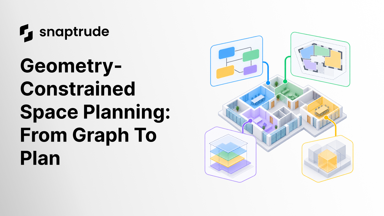
Geometry-constrained space planning converts program relationships into a floor plan while enforcing the physical rules of the project. An adjacency graph says which spaces should connect, but a viable layout must also fit the envelope, respect dimensions and circulation, avoid overlaps, preserve access, and give architects a controlled way to revise the result.
What is geometry-constrained space planning?
Geometry-constrained space planning is the process of arranging required spaces inside a real boundary while satisfying topological, dimensional, circulation, and project-specific rules. It treats the program as more than a list and the adjacency graph as more than a picture. Every relationship must eventually become measurable geometry.
Architectural programming often starts with quantities, target areas, departments, and required connections. A bubble diagram or adjacency matrix can make those relationships legible. It cannot prove that the spaces fit a narrow floor plate, wrap a courtyard, maintain accessible circulation, or preserve a required frontage.
Research on automated floor-plan generation makes this gap explicit. A 2019 method for dimensioned rectangular floor plans combines adjacency relations with minimum widths and aspect-ratio ranges, then uses optimization to find feasible geometry. The adjacency structure is an input, not the finished plan. (Automated Generation of Dimensioned Rectangular Floorplans)
A useful constraint stack has at least five layers:
1. Program constraints: counts, target areas, departments, and priorities
2. Topological constraints: adjacency, separation, connectivity, and sequence
3. Geometric constraints: width, depth, aspect ratio, orientation, and boundary contact
4. Circulation constraints: access, corridor continuity, entry points, and travel logic
5. Decision constraints: accepted rooms, protected zones, preferences, and approval rights
The planning system must show which layer caused a compromise. Otherwise, a failed layout looks like an opaque algorithm problem when it may actually be an impossible brief.
Why is an adjacency graph not enough for a floor plan?
An adjacency graph is not enough because it describes relationships without proving a geometric realization. A graph can say that every operating room should connect to a sterile corridor, or that a shared space should sit between two departments. It does not say whether those rooms fit the available frontage, whether the corridor can reach them, or whether the boundary can be partitioned without overlap.
The problem becomes harder as constraints interact. A room can satisfy its target area but fail its minimum width. Two departments can remain adjacent but block access to a third. A layout can use the full envelope but create unusable leftover slivers. A graph that is valid in the abstract may have no acceptable floor plan under the required dimensions.
The House-GAN research project frames floor-plan generation as graph-constrained layout generation: the input graph represents room types and spatial adjacency, while the output must become room bounding boxes. Its evaluations distinguish realism, diversity, and compatibility with the input graph. That separation is useful for practice because no single score proves a plan is ready. (House-GAN)
More recent research also separates topological planning from geometric realization. GFLAN takes an exterior boundary and door location, places room centroids, then constructs room boundaries through a graph-based model. The authors describe this as a response to the difficulty of combining functional requirements, topology, and geometry in one step. (GFLAN)
Use a floor plan adjacency matrix to record relationships before asking geometry to resolve them.
Explore Snaptrude to see program data and editable geometry in the same design workflow.
Which constraints should a space-planning workflow include?
A space-planning workflow should include every rule that can change whether the result is usable, and it should distinguish hard constraints from preferences. Hard constraints must pass. Preferences should influence ranking. Assumptions should remain visible until the team confirms them.
This table should be project-specific. A healthcare plan, school, office, laboratory, and airport all place different weight on the same relationship. The point is not to hardcode one universal hierarchy. It is to make the hierarchy explicit before options are compared.
How do you turn program relationships into feasible geometry?
Turn program relationships into feasible geometry through a staged loop: validate the brief, establish the envelope, solve topology, realize dimensions, add circulation, inspect failures, and preserve accepted decisions before regenerating.
1. Validate the program
Check counts, target areas, units, hierarchy, and duplicated requirements. Calculate whether the total target area is plausible for the available gross area after circulation and support allowances. Keep assumptions separate from drawn actuals.
2. Establish the boundary and fixed elements
Define the floor plate, cores, entries, shafts, structural exclusions, courtyards, and protected zones. A solver that ignores fixed geometry can produce an attractive diagram that cannot be used.
3. Solve relationships before exact shapes
Create a topological plan that satisfies required connections and separations. Identify which preferences conflict. Do not hide a broken relationship inside a composite score.
4. Add dimensions and frontage
Translate nodes into spaces with minimum widths, aspect ratios, area ranges, and boundary-contact requirements. This is where abstract adjacency becomes a physical claim.
5. Resolve circulation
Test whether every space has a valid access path and whether corridors create unusable remnants. Circulation is not leftover space between rooms. It is a connected system with its own width, continuity, turning, and entry logic.
6. Compare several viable options
Do not rank layouts by area fit alone. Compare adjacency satisfaction, dimensional compliance, circulation quality, daylight opportunity, structural fit, and reviewer effort. Preserve the reasons behind the ranking.
7. Lock accepted decisions and regenerate the rest
Once the architect accepts a location, orientation, or grouping, keep it fixed during the next iteration. This turns generation into collaboration. The system explores unresolved parts while the human remains the author of accepted state.
How should architects review an automated floor plan?
Architects should review an automated floor plan as a proposal with inspectable evidence, not as an answer. The review should identify passed constraints, compromises, unresolved assumptions, and the work required to make the option useful.
Use five review lenses:
• Program fit: Are required spaces, areas, and counts present?
• Geometric fit: Do dimensions, aspect ratios, and boundary contacts work?
• Connectivity: Are required adjacencies and access paths satisfied?
• Editability: Can the architect move, resize, lock, or detach a part without restarting?
• Comparability: Can reviewers understand why one option ranks above another?
A generated option can be mathematically feasible and still be architecturally weak. It may create awkward residual spaces, poor wayfinding, repetitive proportions, or an inflexible structural pattern. These are not reasons to abandon automation. They are reasons to keep human judgment inside the loop and expose enough geometry for that judgment to operate.
See why department-first planning can clarify relationships before room detail.
How does Snaptrude support geometry-constrained space planning?
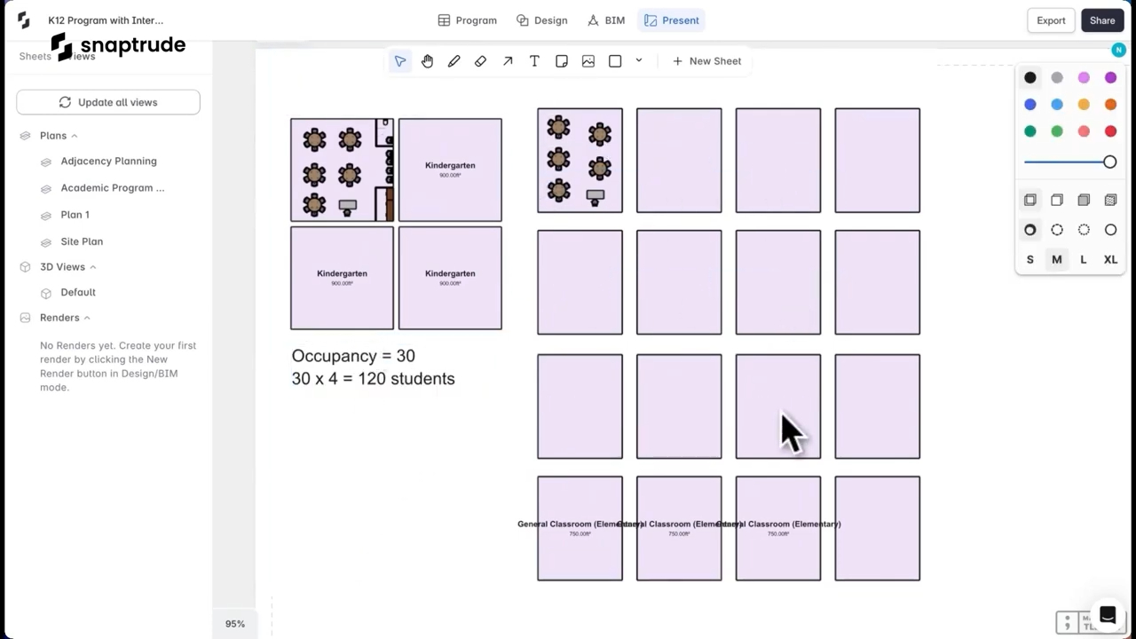
Snaptrude's Program Mode supports architectural programming, area calculations, adjacency planning, and a direct connection from program data to 3D design. Design Mode supports concept modeling, parametric intelligence, real-time 3D visualization, snapping, alignment, and massing studies. BIM Mode carries the selected design into building elements, quantities, schedules, drawings, and IFC export.
Snaptrude AI is in private beta. Demonstrated specialized agents include programming, buildable envelope, circulation, and layout or arrange tasks. The private-beta layout workflow has been shown with multiple options and an architect in control. These capabilities should be evaluated by the quality and editability of the resulting design state, not treated as guaranteed code or planning compliance.
The connected model is important because program targets and geometry can be reviewed together. The architect can inspect what fit, what moved, what remained unresolved, and what should stay fixed in the next iteration.
Read why bubble diagrams need a path into measurable design geometry.
References
Automated Generation of Dimensioned Rectangular Floorplans: Upasani, Shekhawat, and Sachdeva, 2019. The paper combines adjacency relations with minimum width and aspect-ratio constraints to generate feasible dimensioned floor plans.
House-GAN: Relational Generative Adversarial Networks for Graph-constrained House Layout Generation: Nauata and coauthors, 2020. The research maps room and adjacency graphs to geometric layouts and evaluates realism, diversity, and graph compatibility separately.
GFLAN: Generative Functional Layouts: Abouagour and Garyfallidis, 2025. The preprint separates topological planning from geometric realization inside an exterior boundary.
FAQ: Frequently Asked Questions
Q: What is geometry-constrained space planning?
A: Geometry-constrained space planning arranges program spaces inside a real boundary while enforcing adjacency, dimensions, circulation, access, and project-specific rules. It goes beyond a relationship graph by producing measurable geometry. The result should show which constraints passed, which preferences were traded off, and which assumptions still require an architect's judgment.
Q: What is the difference between topology and geometry in a floor plan?
A: Topology describes relationships such as which rooms connect, separate, or follow one another. Geometry describes measurable location, size, shape, orientation, and boundary contact. A topological plan can be valid without fitting the available floor plate. A viable floor plan needs both, plus circulation and project-specific performance checks.
Q: Can every adjacency graph become a floor plan?
A: No. Some graphs cannot be realized within a particular boundary while also satisfying room dimensions, aspect ratios, area requirements, and circulation. Even when a mathematical layout exists, it may not meet architectural expectations. A planning workflow should report infeasibility and the conflicting constraints instead of forcing an opaque compromise.
Q: How should teams score generated floor plans?
A: Score several dimensions separately: program completion, adjacency satisfaction, dimensional compliance, circulation quality, boundary use, daylight opportunity, and editability. Keep hard failures distinct from preferences. A single blended score can hide a serious violation behind several minor strengths, so reviewers should always see the underlying evidence.
Q: Does Snaptrude generate space-planning options?
A: Snaptrude AI has demonstrated private-beta programming, circulation, and layout or arrange agents with an architect in the loop. Snaptrude's verified Program Mode also supports area calculations, adjacency planning, and a connection to 3D design. Generated options should still be reviewed for program fit, geometry, circulation, and editability.
Q: Can architects edit generated layouts in Snaptrude?
A: Snaptrude is an architectural design platform with editable Program, Design, and BIM workflows. Its private-beta AI positioning keeps the architect in control of design decisions. The correct evaluation is practical: test whether the team can inspect, revise, compare, and carry the selected option into BIM and presentation without rebuilding the work.
Explore Snaptrude with one constrained program and judge the options by how much useful, editable design work they preserve.