Last updated:
BIM Cut Plane vs View Range: A Diagnostic Guide
TL;DR
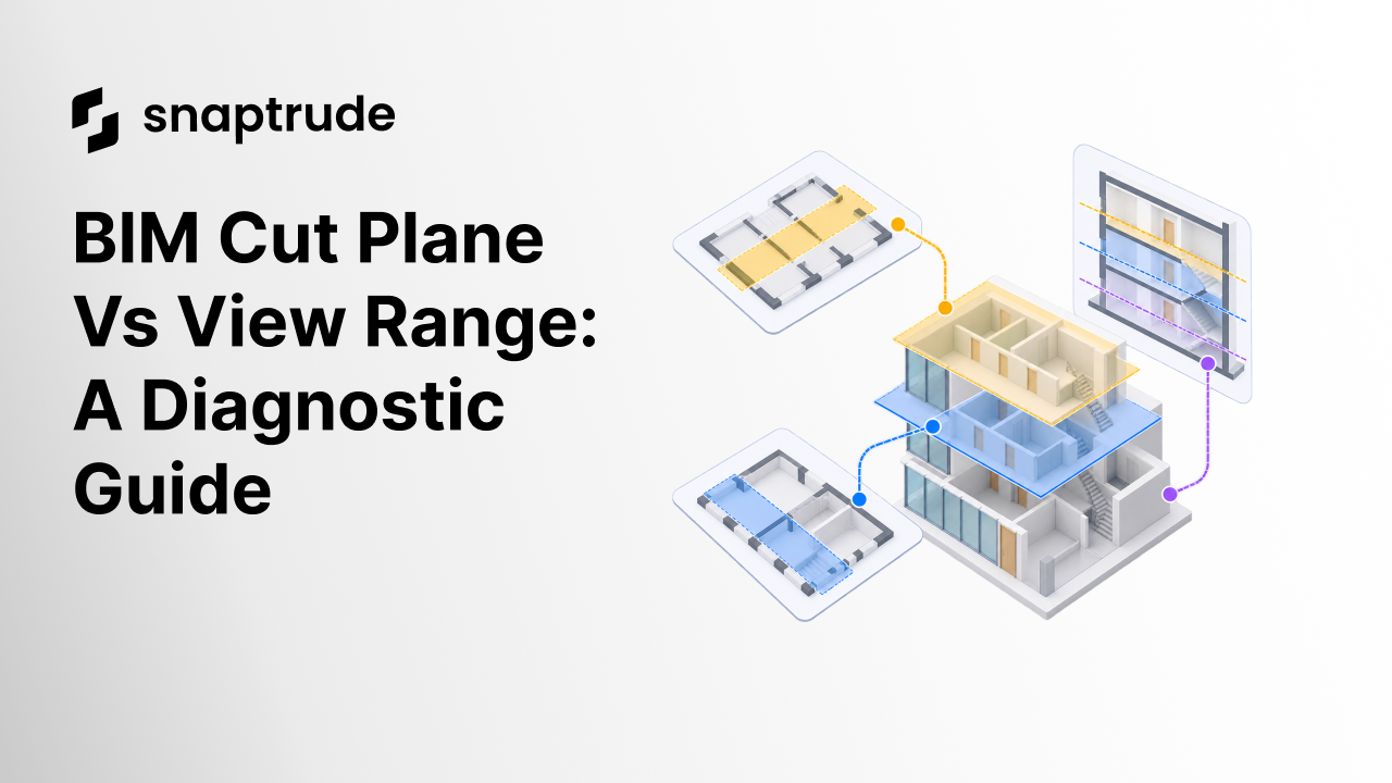
BIM cut plane vs view range is not a choice between two equivalent settings. The cut plane is one boundary inside a larger view range. It determines how intersected objects are represented, while the top, bottom, view depth, underlay, and object rules determine whether other geometry appears at all.
What does BIM cut plane vs view range mean?
BIM cut plane vs view range describes the relationship between the horizontal plane that cuts model elements and the full vertical zone a plan view can display. The cut plane sits inside the primary range. Objects intersected by it normally use cut representation. Objects above or below it may use projection, overhead, beyond, or underlay graphics according to the platform and object category.
Autodesk's Revit documentation defines four horizontal controls for a plan view: Top, Cut plane, Bottom, and View Depth. The top, cut, and bottom planes form the primary range. View depth extends visibility beyond the bottom of that range. This is a useful mental model even when another BIM platform uses different labels. A plan is a rule-based vertical query, not a camera pointed straight down. (Autodesk View Range Properties)
Keep five concepts separate:
1. The cut plane decides which intersected elements receive cut graphics.
2. The primary range defines the main vertical band represented by the plan.
3. The view depth admits selected geometry below the primary range.
4. An underlay supplies reference geometry from another level or state.
5. Object and view rules still control category visibility, phase, option, discipline, and graphic override.
A missing object is therefore not proof that the cut plane is wrong. It may sit outside the range, belong to a hidden category, be assigned to another design option, or appear only through an underlay. Diagnosis starts by identifying the expected representation before changing any height.
How do cut plane, view range, and underlay differ?
Cut plane, view range, and underlay differ in what they control. The cut plane controls intersection. The view range controls vertical eligibility. An underlay adds context that is not part of the active plan's primary representation.
The distinction matters because each control communicates something different to the reader. A wall shown in cut is part of the plan's active spatial boundary. A stair seen below through view depth is context. A level shown as an underlay is a coordination reference. If all three use similar graphics, the drawing may be technically populated but semantically weak.
See how a multi-story 3D view can provide vertical context without pretending to be a plan.
Open one representative floor plan and label five objects as cut, projected, overhead, below-range, or underlaid before changing any view setting.
How should you diagnose BIM cut plane vs view range problems?
Diagnose BIM cut plane vs view range problems by starting with one object, one expected representation, and one section through the same location. Broad changes hide causality. A controlled test reveals which rule actually governs the result.
1. State the expected result
Write down what the object should communicate. Should a window be cut? Should a stair below appear only as context? Should a high-level cabinet use overhead graphics? Should the level above remain absent? “Make it visible” is not a sufficient requirement because several visible states mean different things.
2. Confirm object identity and vertical extent
Check the object's host level, base, top, offsets, bounding geometry, and category. In a section or elevation, compare those extents with the plan's top, cut, bottom, and depth planes. A nominal level assignment does not guarantee that the modeled geometry crosses the same vertical zone.
3. Test the cut intersection
Move a temporary duplicate view's cut plane across the object in a small increment. If representation changes at the expected height, the cut rule is working. If it does not, inspect category-specific behavior, family geometry, symbolic lines, or object state before continuing.
4. Test primary range and depth independently
Restore the cut plane, then vary the bottom and view depth separately. This isolates an object admitted by the primary range from one admitted only as lower context. Record the transition instead of relying on memory.
5. Turn off the underlay
If the object remains, it belongs to another visibility path. If it disappears, confirm that reference graphics are intentionally subordinate and cannot be mistaken for active geometry.
6. Check non-geometric filters
Review category visibility, discipline, detail level, phase, renovation state, design option, workset, crop, scope, filters, and object overrides. A vertical diagnosis is complete only after these independent controls are ruled out.
7. Reopen and print the result
Save the view, reopen it, and check a print or export. Some failures are persistence or output failures rather than viewport failures. The acceptance test should follow the drawing through the representation used for review.
What edge cases make plan visibility harder?
Sloped sites, split levels, tall spaces, stairs, ramps, clerestory openings, multistory elements, and partial-height components make plan visibility harder because one global horizontal range may not express every local condition clearly.
A sloped site is a good example. The same ground surface can sit above the plan range on one side and below it on another. Raising the global cut plane may fix one entrance while corrupting windows, stairs, or walls elsewhere. Use a section to understand the vertical condition first. Then decide whether the drawing needs a local range, a separate plan, a callout, a section, or a controlled reference.
Also test elements whose displayed geometry differs from their physical body. A family may contain symbolic plan lines. A stair may apply category-specific plan conventions. An opening may have no solid geometry at the cut height. These cases do not invalidate the view-range model. They show why the model must be combined with object semantics.
How do you turn view settings into a QA standard?
Turn view settings into a QA standard by testing representative object classes at known heights. A reusable matrix is more dependable than asking reviewers to inspect an arbitrary finished plan.
Build a small validation model containing:
• A wall, door, window, column, furniture item, stair, ramp, opening, and overhead element
• Objects entirely above, intersecting, inside, and below the primary range
• One element admitted only by view depth
• One object supplied only by an underlay
• One phased or option-controlled element
• One sloped or split-level condition
For every row, record expected screen, print, and export behavior. Include cut versus projection graphics, line hierarchy, fill, editability, and whether the object survives save and reopen. When a template changes, rerun the matrix before project teams inherit it.
Review the broader BIM workflow from model development to drawings and coordination.
How does Snaptrude support plan-view diagnosis?
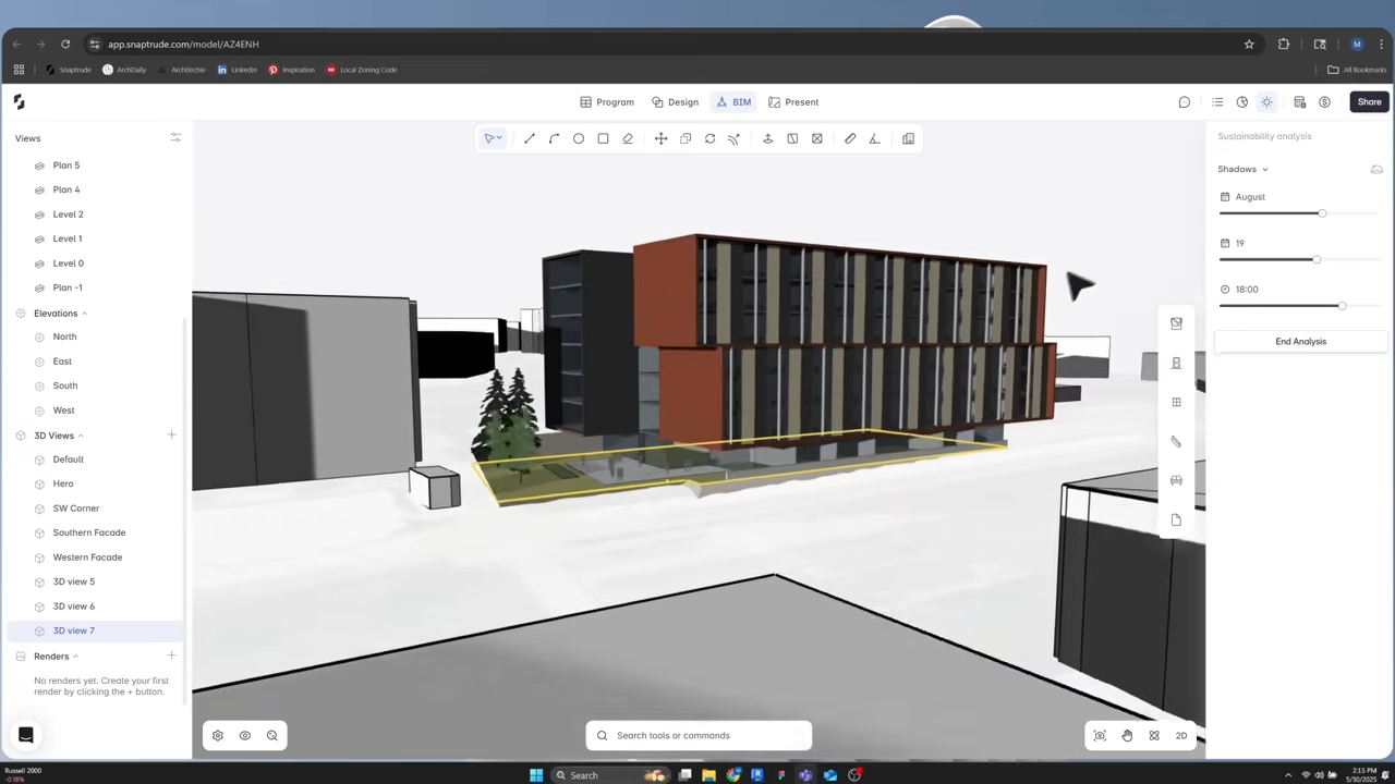
Snaptrude connects 3D design with BIM documentation in a browser-based environment. BIM Mode supports plans, sections, elevations, schedules, drawing creation, annotation, and IFC export. Teams can use the connected model and its representations to compare a plan condition with its vertical geometry and measurable object information.
The software does not remove the need for a view standard. BIM managers still need to define which elements should be cut, projected, referenced, hidden, or shown from another level. The practical advantage of connected representations is that a reviewer can move between plan and spatial context without treating the drawing as an isolated graphic.
Learn why BIM connects geometry and information rather than stopping at a drawing.
References
View Range Properties: Autodesk documentation defining Top, Cut plane, Bottom, View Depth, and the primary range in a plan view.
About the View Range: Autodesk's 2026 documentation describing how view range affects object display in plan and reflected ceiling plan views.
Frequently Asked Questions About BIM Cut Plane vs View Range
Q: What is the difference in BIM cut plane vs view range?
A: The cut plane is one horizontal boundary inside the larger view range. It controls how intersected model elements are represented, usually with cut graphics. The view range includes top, cut, bottom, and often an additional view-depth boundary. Together they determine which vertical geometry can appear and whether it is cut, projected, overhead, or shown as lower context.
Q: Why is an object missing even when it crosses the cut plane?
A: An object can cross the expected height and still be hidden by its category, phase, design option, workset, discipline, crop, filter, detail level, family representation, or object override. Confirm its geometry in section, then isolate vertical settings from non-geometric visibility rules. Testing one duplicate view prevents a broad template change from concealing the actual cause.
Q: Is view depth the same as an underlay?
A: No. View depth extends the active view's vertical reach below the primary range and normally applies a lower-context representation. An underlay references another level or view state for coordination. Both can reveal geometry beyond the main plan, but they have different sources, graphic purposes, and editing implications. They should remain visually distinguishable in a reviewed drawing.
Q: Should I raise the cut plane to make a window visible?
A: Raise the cut plane only after confirming that the intended drawing should cut that window and that the change will not damage other representations. Check the window's actual geometry, sill, host, symbolic plan content, and category behavior first. Test the change in a duplicate view and review doors, stairs, walls, openings, and annotation before applying it to a shared template.
Q: How should split levels be shown in plan?
A: Start with a section that establishes the vertical relationships, then choose the clearest plan strategy for each local condition. A global range may not communicate several floor elevations well. Depending on the platform and documentation standard, use a local range, separate plan, callout, section, or controlled underlay. The chosen representation should make active geometry and reference context unambiguous.
Q: How can Snaptrude help diagnose plan visibility?
A: Snaptrude connects BIM plans, sections, elevations, schedules, and 3D model context. That connection lets a team compare a plan result with the object's vertical position and related information instead of reviewing a flat drawing alone. Project standards still determine the intended cut, projection, reference, and hidden states, and those standards should be tested before broad template use.
Test one plan-view matrix in Snaptrude, compare it with the corresponding section and 3D context, and record the intended representation for every object class.