Last updated:
BIM Display Order vs Model Geometry: Diagnose the Right Problem
TL;DR
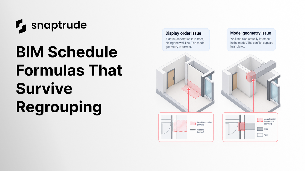
BIM display order vs model geometry is the difference between changing how objects look in one representation and changing what the building actually contains. Diagnose the view, object type, and persistence of the overlap before moving, trimming, or deleting geometry.
What does BIM display order vs model geometry mean?
BIM display order vs model geometry separates two very different failure classes. A display-order problem changes which line, region, annotation, image, or detail appears in front. A geometry problem means physical model elements occupy the wrong location, intersect incorrectly, or have the wrong extents.
The screen can make those failures look identical. A filled region can cover a wall line. A detail item can sit above modeled construction. A transparent surface can reveal edges that appear to be clashes. A hidden category can make a correctly modeled object disappear. None of those conditions proves that the model geometry is wrong.
Autodesk's Revit documentation makes one boundary explicit: detail elements always appear on top of model geometry, while their order can be changed relative to other details. Its visibility documentation separately describes category, filter, and element overrides for model display. Those are representation controls, not operations that relocate the building. (Autodesk on draw order)
Start by naming the object on each side of the overlap. Is it model geometry, a model-linked symbol, a view-specific detail, an annotation, an imported layer, or a raster image? The answer determines which controls are valid and which apparent fixes would damage the source model.
How can you tell a BIM display order problem from a geometry conflict?
You can tell them apart by testing whether the condition changes with the view while the objects remain in the same modeled location. A display problem is usually view-dependent. A geometry conflict usually survives in another plan, section, elevation, or 3D inspection because the underlying bodies still intersect.
Do not begin with the most powerful edit. Begin with the smallest reversible test. Duplicate the affected view, isolate the two objects, and inspect the same location in a section or 3D view. If the physical relationship is correct outside the problem view, return to visibility and graphic rules.
This distinction also changes who should own the fix. A project architect may need to resolve an actual wall-slab intersection. A BIM manager may need to adjust a view template or family convention. A documentation lead may need to reorder a detail group. Treating every overlap as geometry sends the problem to the wrong person and creates unnecessary model risk.
See how BIM connects geometry and information instead of stopping at a flat drawing.
Choose one recurring overlap in your current drawing set and classify both objects before editing either one.
What diagnostic sequence prevents destructive geometry edits?
Use a fixed sequence that moves from representation to model state. The goal is to establish causality, not merely make the symptom disappear.
1. Record the expected visual result
State which object should read first and why. A cut wall, a room boundary, a fire-rating symbol, and a poche region each carry a different kind of information. “Bring this forward” is a command, not a design requirement. The expected result should describe what the drawing must communicate.
2. Classify both objects
Select each object and record whether it is modeled, view-specific, annotation, detail, linked, imported, or image-based. If one object is not part of the physical model, a geometric operation is unlikely to be the right first response.
3. Isolate the view rules
Check category visibility, view filters, element overrides, phase, design option, detail level, discipline, transparency, halftone, hidden-line behavior, and linked-file display. Autodesk documents that these controls can act at project, category, filter, or individual-element levels, so the visible result may come from several layers of precedence. (Autodesk on visibility and graphic display)
4. Compare another representation
Open a section through the overlap and a 3D view with both objects isolated. Measure their extents. If they do not intersect there, the plan symptom is representational. If they do, inspect joins, offsets, hosts, constraints, and intended construction before changing anything.
5. Apply one reversible change
Change one display control in a duplicated view. Do not simultaneously move geometry, change a family, and edit a template. A single-variable test gives you evidence. Multiple changes give you a temporarily cleaner screen and no reliable diagnosis.
6. Test persistence and output
Save, reopen, and check the same view in PDF or another required output. Then inspect a second view that should remain unchanged. A valid fix survives persistence, communicates correctly in output, and does not create a new problem elsewhere.
This sequence is small enough to become a team standard. Put it beside the model-health checklist and require a screenshot or short note for changes that alter shared view templates or reusable content.
Why do view-specific graphics create false geometry alarms?
View-specific graphics create false alarms because they borrow the visual language of physical objects. A masking region can hide an edge. A detail line can look like modeled construction. A filled region can make two boundaries appear joined. Imported CAD can introduce duplicate lines. The drawing looks spatial, but some of its content has no physical depth.
The risk increases when object identity is hard to inspect. If a user cannot quickly tell whether the selected line is part of a wall, a detail component, a group, a linked file, or an overlay, the safest response becomes guesswork. Good BIM interfaces should make object type, view scope, and applicable commands obvious before the edit is committed.
A team standard should therefore define not only lineweights and colors, but also authorship rules:
1. Which information must be modeled?
2. Which information may be view-specific?
3. Which details can mask model edges?
4. Which imported files are permitted in production views?
5. Which overrides belong in templates rather than individual views?
6. How is a deliberate exception recorded?
When should you change BIM display order vs model geometry?
Change BIM display order when the modeled relationship is correct and the problem is limited to graphic precedence or visibility. Change model geometry only when another spatial representation, measurement, or quantity confirms that the physical relationship is wrong.
There is one useful escalation rule: if a proposed display fix changes quantities, dimensions, hosted relationships, or coordination in another view, it is no longer only a display fix. Stop and review the model impact.
The reverse is also true. If a proposed geometry fix exists only to make one drawing read correctly, ask whether the drawing needs a representation rule instead. The model should describe the building, while the view should communicate the right slice of that model for a specific task.
How should teams test display-order behavior before rollout?
Build a small reference file that contains representative model objects, overlapping detail items, filled and masking regions, linked or imported content, annotations, and images. Test the file against every shared view template and required output.
For each case, record:
• Object types on both sides of the overlap
• Expected front-to-back relationship
• Controls that are available for those object types
• Behavior in plan, section, elevation, and 3D
• Screen, print, and export parity
• Save and reopen behavior
• Effect on quantities, dimensions, and selection
Use intentionally awkward cases. Rotate a group, nest a detail inside reusable content, overlap transparent model faces, and place a detail over a linked model. The point is not to make a beautiful test model. It is to reveal where object semantics, precedence, and output behavior diverge.
When a software update or template revision changes the result, the matrix gives the team a reproducible failure rather than a vague report. That reduces the temptation to patch the visible drawing with extra lines or geometry.
How does Snaptrude support the right diagnosis?
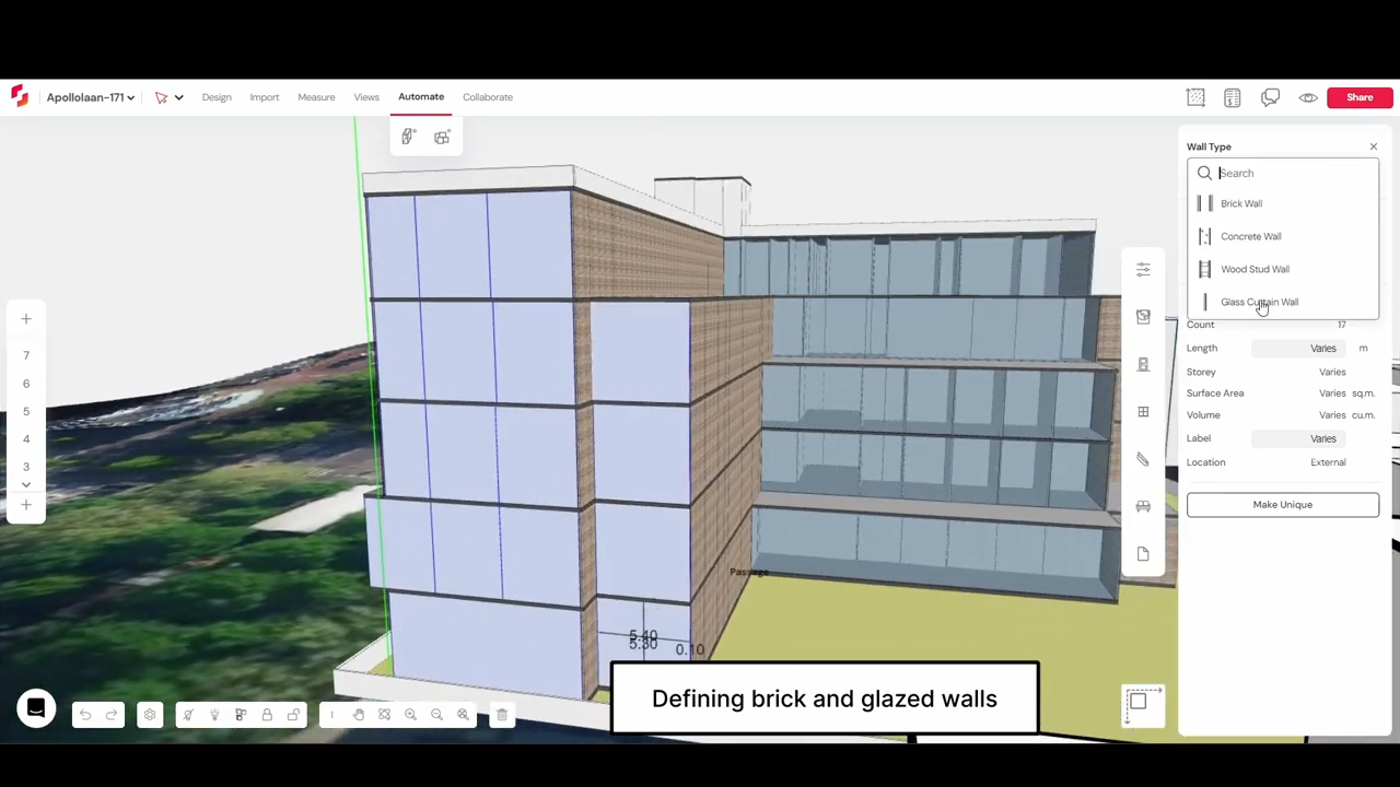
Snaptrude connects browser-based BIM modeling with plans, sections, elevations, schedules, drawing creation, annotation, 3D views, and presentation. Teams can move between a suspect drawing condition and its spatial context without rebuilding the design in a separate tool.
Snaptrude also supports real-time multiplayer collaboration, comments, automatic version history, and branching with merge workflows. Those verified capabilities help reviewers discuss a condition, compare model states, and preserve the history of a correction. They do not replace a project display standard or make every overlap automatic. The team still decides which information is geometric, which is representational, and what acceptance evidence is required.
Learn how Present Mode keeps review views close to the design model.
References
About the Draw Order of Details: Autodesk Revit 2026 documentation defining how detail elements stack relative to other details and model geometry.
Visibility and Graphic Display in Project Views: Autodesk Revit 2026 documentation covering project, category, filter, and element-level display controls.
Frequently Asked Questions About BIM Display Order vs Model Geometry
Q: What is the difference between BIM display order and model geometry?
A: Display order controls which supported graphic or detail element appears in front within a view. Model geometry describes the physical size, location, and relationship of building elements. A display change can correct a drawing without changing the building model. A geometry change affects spatial coordination, measurements, quantities, and potentially every view that represents the edited object.
Q: How do I know whether an overlap is only a view problem?
A: Duplicate the view, isolate both objects, and inspect the same location in section and 3D. If the relationship is correct there but changes with visibility, overrides, detail content, or a view template, the problem is probably representational. If the physical bodies still intersect and measurements confirm the conflict, treat it as a geometry issue and review the intended construction.
Q: Can a masking region safely fix a BIM clash?
A: A masking region can improve a specific drawing when the underlying geometry is already correct and the masking convention is documented. It cannot resolve a physical clash. Before using one, verify the objects in another representation and check quantities and dimensions. If the mask merely conceals incorrect geometry, it transfers the problem to coordination, documentation, or construction instead of solving it.
Q: Why does display order work for some objects but not others?
A: Display-order commands usually apply to defined view-specific or detail object classes, not to every modeled element. Model elements are governed by depth, cut and projection rules, category visibility, material display, and view overrides. Imported content and nested families can add their own constraints. Classify the selected object first, then use only the controls that belong to that object and view.
Q: How can Snaptrude help investigate a suspected geometry conflict?
A: Snaptrude connects BIM plans, sections, elevations, schedules, and 3D views in a browser-based environment. A reviewer can compare the drawing symptom with the model's spatial context and measurable information. Comments and automatic version history can preserve the discussion and correction. The project team still defines the expected representation and decides whether the final change belongs to geometry or display.
Q: Does Snaptrude automatically resolve BIM display order problems?
A: Snaptrude provides connected modeling and documentation capabilities, but a team must still define drawing standards and validate object behavior. Treat display order as a diagnosable state: identify the objects, compare views, apply one controlled change, and check output. Where a condition reflects real geometry, correct the model. Where it reflects representation, keep the fix scoped to the intended view or standard.
Test one recurring overlap in Snaptrude across plan, section, 3D, save, reopen, and output before changing a shared model or template.